
| As PCB signal switching speeds increase today's PCB designer needs to understand and control the impedance of PCB traces. With the short signal transition times and high clock rates of modern digital circuitry, PCB traces need to be considered not as simple connections but as transmission lines. What is controlled impedance? Probably the most common example of a controlled impedance component is the downlead (or feeder) connecting a receiving aerial to a wireless or television set. Aerial feeder leads usually take the form of "flat twin" cable (commonly supplied with VHF broadcast receivers) or low-loss coaxial cable. In both cases the impedance of the feeder is controlled by the physical dimensions and material of the cable. | |
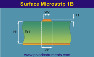 | You can think of PCB traces as short cables, precisely constructed, connecting the devices mounted on the board, where the PCB trace, like the coax inner conductor, carries the signal and is insulated from its return path (in this case a ground plane) by the board laminate. This is shown in cross section in the microstrip configuration, left. |
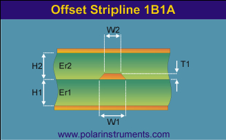 | The dimensions for trace width W1 and W2, thickness T1 and laminate height H1 and H2 and the dielectric constants Er1 and Er2must be strictly controlled. Solder resist on the surface reduces the impedance slightly so the more predictable stripline configuration shown left is often used. |
| So why do we need to control impedance? The receiving aerial possesses a natural, or characteristic, impedance and electrical theory shows that for the aerial to transfer maximum power to the set (and to ensure the integrity of the electrical signal) the impedance both of the feeder and the receiver should match that of the aerial. In other words the signal should ideally be presented with a constant impedance as it travels from its source to its destination. Where a mismatch occurs only part of the signal will be transmitted; the rest will be reflected toward the source (this degrades the signal). Cable designers therefore take great care to ensure the accuracy and consistency of the cable dimensions and material characteristics. At high signal switching speeds, the electrical properties of the cable, such as the capacitance and inductance, must be taken into account, and cables can no longer be considered as simple wires. Cables designed for high signal speeds where these factors are taken into consideration are referred to as transmission lines. Controlled impedance on PCBs Similarly, as the speed of signal switching on a PCB increases, the electrical properties of the traces carrying signals between devices become increasingly more important. The impedance of a PCB trace is controlled by
As with a cable, when the signal encounters a change of impedance arising from a change in material or geometry, part of the signal will be reflected and part transmitted. These reflections are likely to cause aberrations on the signal which may degrade circuit performance (e.g. low gain, noise and random errors). In practice board designers will specify impedance values and tolerances for board traces and rely on the PCB manufacturer to conform to the specification. Testing the PCB Most controlled impedance PCBs undergo 100% testing. However, it is not uncommon for the actual PCB traces to be inaccessible for testing. In addition, traces may be too short for accurate measurement and may well include branches and vias which would also make exact impedance measurements difficult. Adding extra pads and vias for test purposes would affect performance and occupy board space. PCB testing is therefore normally performed, not on the PCB itself, but on one or two test coupons integrated into the PCB panel. The coupon is of the same layer and trace construction as the main PCB and includes traces with precisely the same impedance as those on the PCB, so testing the coupon affords a high degree of confidence that the board impedances will be correct. Measuring controlled impedance Impedance measurements are usually made with a time domain reflectometer (TDR). The TDR applies a fast voltage step to the coupon via a controlled impedance cable and probe. Any reflections in the pulse waveform are displayed on the TDR and indicate a change in impedance value (this is known as a discontinuity). The TDR is able to indicate the location and scale of discontinuity. Using appropriate software the TDR can be made to plot a graph of the impedance over the length of the test trace on the coupon. The resulting graphical representation of the trace characteristic impedance allows previously complex measurements to be performed in a production environment. | |
Wednesday 21 April 2010
Controlled Impedence PCBs with test coupon
Tuesday 26 May 2009
Compliance News
The two year transition period of the new EMC Directive released in 2007 will expire in July 2009. At the very minimum, manufacturers should examine their documentation and ensure that their Declaration of Conformity is updated to reflect the changes. The designation of the new Directive is 2004/108/EC.
Products tested and declared compliant within the last two years will almost certainly conform to the new Directive. If you are in any doubt, then you should consult your testing laboratory.
EMC emissions on network cables
Testing on network cables was introduced into the the base standard EN55022 in 2007. This test is not only specific to products that communicate using telephone lines (PSTN) and Ethernet, but also potentially includes RS485, CAN bus and even audio loudspeaker PA systems.
Compliance with the standard becomes mandatory in October 2009.
Low Voltage Directive updated
An update in the Low Voltage Directive has meant a change in the stated number to 2006/95/EC. Declarations of Conformity should be amended to reflect the changes. There are no specific alterations to testing, procedures or legislation associated with this update, which appears to be nothing more than a consolidation of the previous Directives and subsequent amendments.
Microwave Immunity Testing
Radiated immunity testing above 1GHz appears to have been universally adopted. It is expected that any new immunity standards will feature testing at microwave frequencies. The residential, commercial and light industrial generic standard EN61000-6-1 has now introduced testing at microwave frequencies, which will become mandatory later this year.
Batteries Directive 2006/66/EC Introduced
A Directive specifically targeted at batteries was introduced last year. Although much of the Directive is centred around toxic material content and disposal, there are some relevant points for manufacturers of electronic products. In general, any battery operated product must allow the user to replace or remove batteries. Instruction manuals are required to detail the removal and replacement procedures.
Friday 24 October 2008
| |||||
 Its instigator calls it “the ultimate, ultimate engineering challenge”; it’s driver says it will be “an inspiration for every school child”. It will cost £10 million, reach 1000mph and is called Bloodhound SSC (super sonic car).
Tuesday 9 September 2008
Off-shoring - The Bottom Line

Today the BBC launched a year long project following a 40-foot shipping container as it begins its worldwide journe y from Southampton. The project, called The Box, will follow the container as it transports real goods, from car parts to footwear, in a genuine snapshot of global trade.
80% of goods arriving in Britain do so via container, and for every five full containers received, only one ships out.
Does this mean that the logical approach is for SME's to look east for their manufacturing requirements? Well I hear plenty of anecdotal evidence suggesting that the trend for off-shoring is actually reversing, especially among smaller OEMs so I spoke to a confident at a well known UK 'out-sourcing' company and asked their opinion.
I was surprised to hear at first hand how challenging and time consuming it is to work with an overseas manufacturer.
* Firstly, you have to find the right contractor, so no order should ever be placed without visiting the prospective production facility.
* Following the order, the contractor will then want their money up front before commencing procurement, which can easily take a week.
* Materials lead-time can then be up to 16 weeks and often may require European style components to be shipped out.
* Manufacturing will then be 2-3 weeks and shipping a further 4 weeks.
So there you have up to 30 weeks before the product begins to generate income from the original investment, and remember to add in a dedicated resource to manage the off-shore supply chain, which can be a full time job.
I was amazed to learn that this outsourcing company only has TWO customers for whom they import electronic assemblies from China. Most of their revenue is from smaller items such as electromechanical and wound components.
I questioned why more companies were not jumping to benefit from the savings that China could presumably offer. However this, I was told, was precisely the problem. Expectations of cost reductions are often not realised because OEMs take a far too simplistic view from the offset and do not realise the high costs associated with the supplier management. They are rarely able to forecast demand accurately for competitive batch sizes and are bewildered when a manufacturer will typically ask a hundred questions before commencing a build, with all the language barriers, cultural differences, time zones and legal systems at play.
There is little peace of mind even after delivery. Locally sourced components such as capacitors can have different characteristics over time compared with branded product, let alone the usual risks of sub-stand materials being used (take a look at the ERAI report on our website for the propensity of Chinese open market parts to be less than perfect).
So OEMs who are looking solely at the lowest cost often overlook other factors that give them the ability to serve customers rapidly with high-quality products.
To me the bottom line is, unless you are producing low cost commodity items, find yourself a good UK contract manufacturer!
Thursday 28 August 2008
Voice to Email - Spinvox
I am recently enjoying a great application from Spinvox which allows me to send myself minutes of meetings or general reminders while I'm out and about.
What Spinvox allows you to do is dial a phone number and you are then prompted to leave a message. This voice message is converted into text and can be either emailed to you, update your blog, or can be sent as a text message and email to your friends.
After testing this I have found that as long as you speak at a normal sort of speed and speak clearly the service works very well.
The email service is free to use. You pay for the cost of dialling the access number but the one I was given is a standard UK national number so included in the free minutes on my mobile call package.
You can find out details on Spinvox here
Monday 4 August 2008
Stand at Subcon 08


Friday 25 July 2008
Distributor Shrinking Pains
This year's decline in manufacturing investment in the UK has seen a spectacular share price fall for components distributor Electrocomponents (RS to you and me). For the first time that I can remember their stock is now less than that of their historical rival Farnell. Over the last 20 years RS has always been around three times larger than Farnell, but now their market capitalisation is almost identical. Both companies are headlining 'massive' discounts on their websites but I sense this is alien to the RS mindset and they have much more work to do. RS may be the M+S of the component world so stick around for butchery or buyouts.

